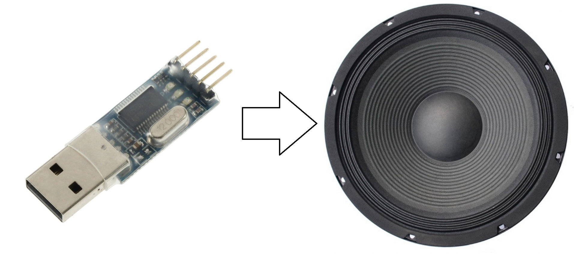
Во время очередной ревизии радиоэлектронного барахла и распихивания по коробочкам мне попался контроллер AVR atxmega256a3u. Дабы развеять скуку было решено сделать некое подобие звуковой карты, а точнее ЦАП, подключаемый к компьютеру. Что из этого получилось смотрите под катом.
Линейка микроконтроллеров XMEGA является развитием знакомых большинству любителей электроники контроллеров MEGA, добавлено много интересных плюшек, но все описанное ниже можно реализовать на традиционной серии. Рекомендую лишь использовать те контроллеры, где побольше ОЗУ.
От слов к разработке, поразмыслив пришел к такой структуре устройства:

Буду воспроизводить музыку из WAV-файлов, моно, 8 бит с частотой дискретизации 44.1 кГц. Посылка последовательного порта состоит из 10 бод (стартовый и стоповый биты, 8 битов данных), значит требуется скорость не ниже 441 кБод/с. Аппаратура позволяет работать быстрее, беру с запасом скорость передачи данных 2000 кБод/с.
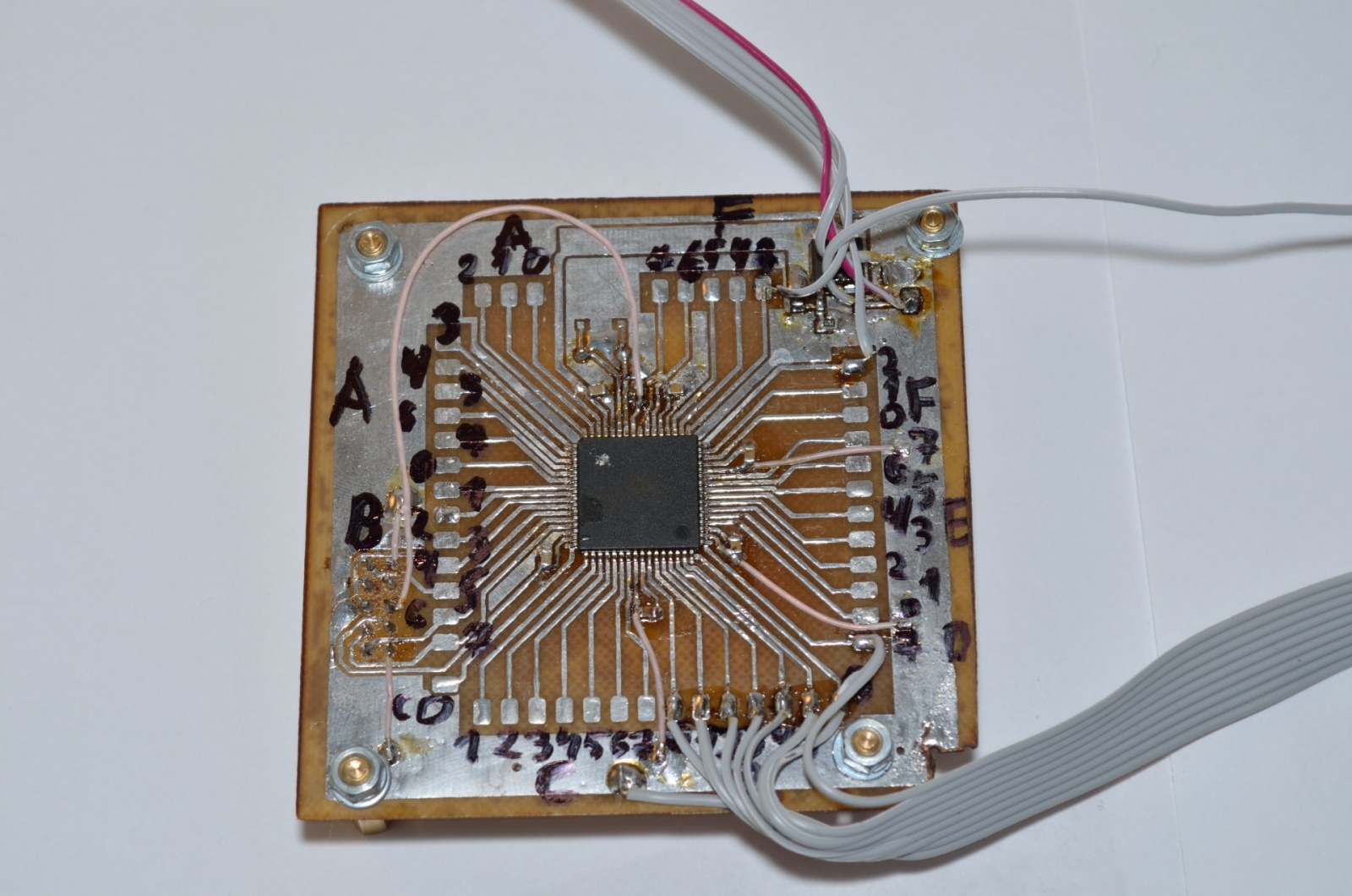
Внутри контроллера буфер FIFO, он же очередь «первый пришел — первый вышел». По таймеру с частотой 44.1 кГц запускается прерывание извлекающее из буфера очередной отсчет и передающее его цифро-аналоговому преобразователю, а также по необходимости выполняется запрос очередного пакета данных у ЭВМ. Размышляя обо всем этом трассирую и травлю «отладочную» плату для микроконтроллера:
Самым интересным в этой разработке пожалуй является ЦАП. В моем микроконтроллере есть встроенный ЦАП, но использовать его не спортивно, к тому же в большинстве микроконтроллеров такой роскоши нет. Ничего страшного, ЦАП можно сделать самому из горсти резисторов по схеме R-2R:

Такая схема позволяет получить на выходе напряжения в диапазоне от 0 В до уровня логической единицы, в моем случае это 3.3 В. Сделаю восьмибитный ЦАП, у меня под рукой лишь резисторы с допустимым отклонением 5%, а значит точность потеряется с пятого разряда поскольку (1/2^5)<0.05. Тем не менее, надеюсь, что младшие разряды позволят озвучить слабые спектральные составляющие сигнала. Собираю из резисторов номиналом 5.1 кОм вот такого монстра:
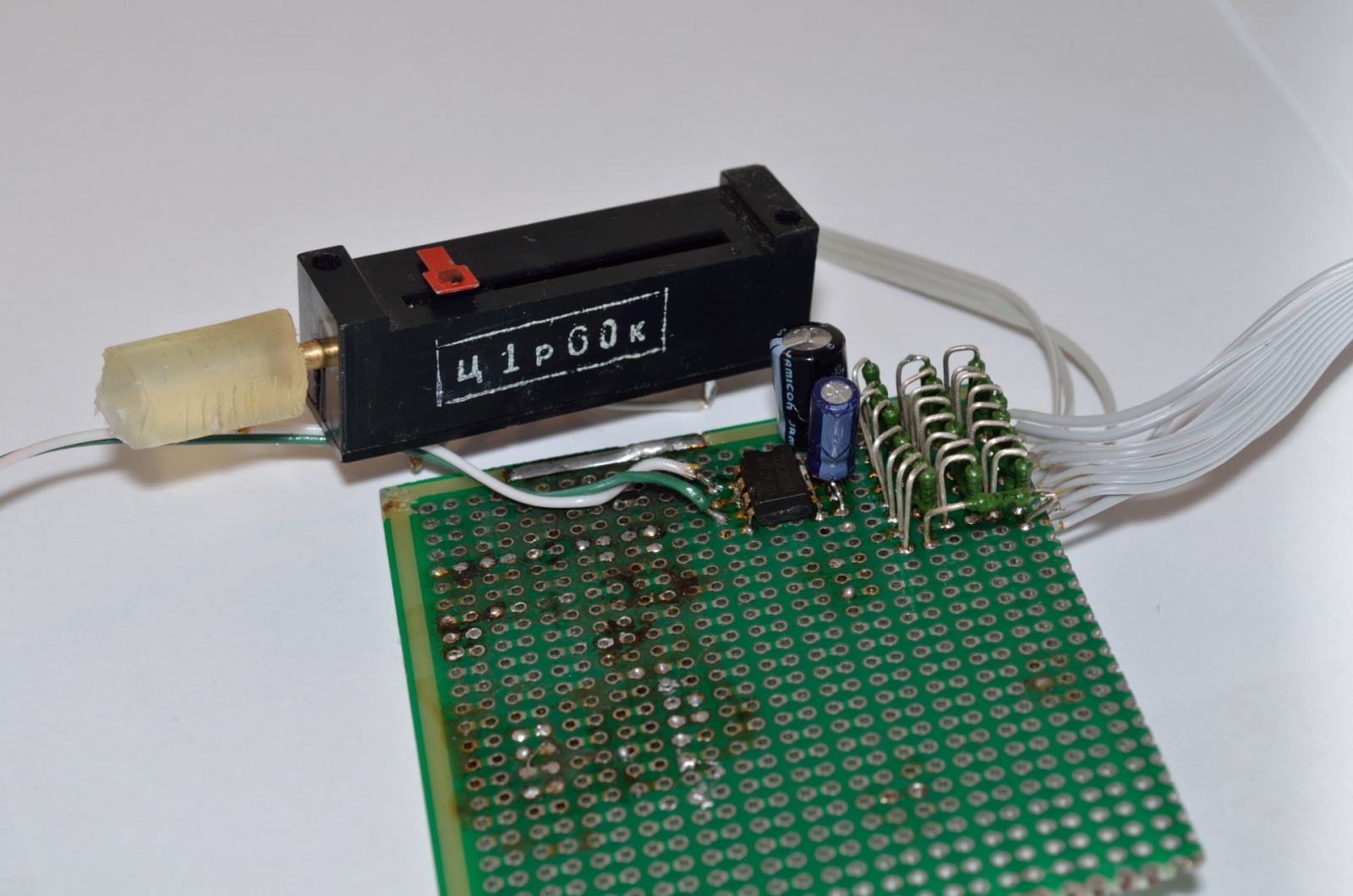
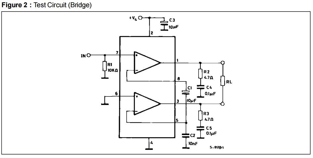
Тут же ставлю усилитель TDA2822M, подключаю по мостовой схеме из даташита:
И делаю колонку с фазоинвертором:
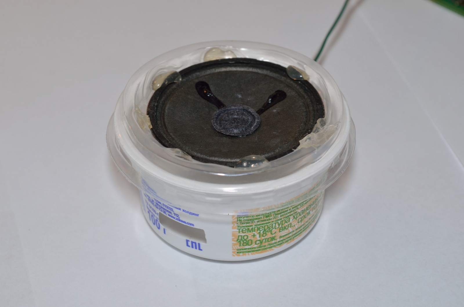
Пора послушать:
Звучит более-менее терпимо, если подключить динамик побольше становится получше.
// I/O Registers definitions
#include <io.h>

// Declare your global variables here
#define fSIZE 12000
int rAdr,wAdr,dn;
char needdata;
char fifo[fSIZE];
// System Clocks initialization
void system_clocks_init(void)
{
unsigned char n,s;

// Optimize for speed
#pragma optsize-
// Save interrupts enabled/disabled state
s=SREG;
// Disable interrupts
#asm("cli")

// External 16000,000 kHz oscillator initialization
// External Clock Source - Startup Time: 0.4-16 MHz Quartz Crystal - 16k CLK
OSC.XOSCCTRL=OSC_FRQRANGE_12TO16_gc | OSC_XOSCSEL_XTAL_16KCLK_gc;
// Enable the external oscillator/clock source
OSC.CTRL|=OSC_XOSCEN_bm;

// System Clock prescaler A division factor: 1
// System Clock prescalers B & C division factors: B:1, C:1
// ClkPer4: 16000,000 kHz
// ClkPer2: 16000,000 kHz
// ClkPer:  16000,000 kHz
// ClkCPU:  16000,000 kHz
n=(CLK.PSCTRL & (~(CLK_PSADIV_gm | CLK_PSBCDIV1_bm | CLK_PSBCDIV0_bm))) |
	CLK_PSADIV_1_gc | CLK_PSBCDIV_1_1_gc;
CCP=CCP_IOREG_gc;
CLK.PSCTRL=n;

// Wait for the external oscillator to stabilize
while ((OSC.STATUS & OSC_XOSCRDY_bm)==0);

// Select the system clock source: External Oscillator or Clock
n=(CLK.CTRL & (~CLK_SCLKSEL_gm)) | CLK_SCLKSEL_XOSC_gc;
CCP=CCP_IOREG_gc;
CLK.CTRL=n;

// Disable the unused oscillators: 2 MHz, 32 MHz, internal 32 kHz, PLL
OSC.CTRL&= ~(OSC_RC2MEN_bm | OSC_RC32MEN_bm | OSC_RC32KEN_bm | OSC_PLLEN_bm);

// ClkPer output disabled
PORTCFG.CLKEVOUT&= ~(PORTCFG_CLKOUTSEL_gm | PORTCFG_CLKOUT_gm);
// Restore interrupts enabled/disabled state
SREG=s;
// Restore optimization for size if needed
#pragma optsize_default
}

// Ports initialization
void ports_init(void)
{
// PORTA initialization
// OUT register
PORTA.OUT=0x00;
// Pin0: Input
// Pin1: Input
// Pin2: Input
// Pin3: Input
// Pin4: Input
// Pin5: Input
// Pin6: Input
// Pin7: Input
PORTA.DIR=0x00;
// Pin0 Output/Pull configuration: Totempole/No
// Pin0 Input/Sense configuration: Sense both edges
// Pin0 Inverted: Off
// Pin0 Slew Rate Limitation: Off
PORTA.PIN0CTRL=PORT_OPC_TOTEM_gc | PORT_ISC_BOTHEDGES_gc;
// Pin1 Output/Pull configuration: Totempole/No
// Pin1 Input/Sense configuration: Sense both edges
// Pin1 Inverted: Off
// Pin1 Slew Rate Limitation: Off
PORTA.PIN1CTRL=PORT_OPC_TOTEM_gc | PORT_ISC_BOTHEDGES_gc;
// Pin2 Output/Pull configuration: Totempole/No
// Pin2 Input/Sense configuration: Sense both edges
// Pin2 Inverted: Off
// Pin2 Slew Rate Limitation: Off
PORTA.PIN2CTRL=PORT_OPC_TOTEM_gc | PORT_ISC_BOTHEDGES_gc;
// Pin3 Output/Pull configuration: Totempole/No
// Pin3 Input/Sense configuration: Sense both edges
// Pin3 Inverted: Off
// Pin3 Slew Rate Limitation: Off
PORTA.PIN3CTRL=PORT_OPC_TOTEM_gc | PORT_ISC_BOTHEDGES_gc;
// Pin4 Output/Pull configuration: Totempole/No
// Pin4 Input/Sense configuration: Sense both edges
// Pin4 Inverted: Off
// Pin4 Slew Rate Limitation: Off
PORTA.PIN4CTRL=PORT_OPC_TOTEM_gc | PORT_ISC_BOTHEDGES_gc;
// Pin5 Output/Pull configuration: Totempole/No
// Pin5 Input/Sense configuration: Sense both edges
// Pin5 Inverted: Off
// Pin5 Slew Rate Limitation: Off
PORTA.PIN5CTRL=PORT_OPC_TOTEM_gc | PORT_ISC_BOTHEDGES_gc;
// Pin6 Output/Pull configuration: Totempole/No
// Pin6 Input/Sense configuration: Sense both edges
// Pin6 Inverted: Off
// Pin6 Slew Rate Limitation: Off
PORTA.PIN6CTRL=PORT_OPC_TOTEM_gc | PORT_ISC_BOTHEDGES_gc;
// Pin7 Output/Pull configuration: Totempole/No
// Pin7 Input/Sense configuration: Sense both edges
// Pin7 Inverted: Off
// Pin7 Slew Rate Limitation: Off
PORTA.PIN7CTRL=PORT_OPC_TOTEM_gc | PORT_ISC_BOTHEDGES_gc;
// Interrupt 0 level: Disabled
// Interrupt 1 level: Disabled
PORTA.INTCTRL=(PORTA.INTCTRL & (~(PORT_INT1LVL_gm | PORT_INT0LVL_gm))) |
	PORT_INT1LVL_OFF_gc | PORT_INT0LVL_OFF_gc;
// Pin0 Pin Change interrupt 0: Off
// Pin1 Pin Change interrupt 0: Off
// Pin2 Pin Change interrupt 0: Off
// Pin3 Pin Change interrupt 0: Off
// Pin4 Pin Change interrupt 0: Off
// Pin5 Pin Change interrupt 0: Off
// Pin6 Pin Change interrupt 0: Off
// Pin7 Pin Change interrupt 0: Off
PORTA.INT0MASK=0x00;
// Pin0 Pin Change interrupt 1: Off
// Pin1 Pin Change interrupt 1: Off
// Pin2 Pin Change interrupt 1: Off
// Pin3 Pin Change interrupt 1: Off
// Pin4 Pin Change interrupt 1: Off
// Pin5 Pin Change interrupt 1: Off
// Pin6 Pin Change interrupt 1: Off
// Pin7 Pin Change interrupt 1: Off
PORTA.INT1MASK=0x00;

// PORTB initialization
// OUT register
PORTB.OUT=0x00;
// Pin0: Input
// Pin1: Input
// Pin2: Input
// Pin3: Input
// Pin4: Input
// Pin5: Input
// Pin6: Input
// Pin7: Input
PORTB.DIR=0x00;
// Pin0 Output/Pull configuration: Totempole/No
// Pin0 Input/Sense configuration: Sense both edges
// Pin0 Inverted: Off
// Pin0 Slew Rate Limitation: Off
PORTB.PIN0CTRL=PORT_OPC_TOTEM_gc | PORT_ISC_BOTHEDGES_gc;
// Pin1 Output/Pull configuration: Totempole/No
// Pin1 Input/Sense configuration: Sense both edges
// Pin1 Inverted: Off
// Pin1 Slew Rate Limitation: Off
PORTB.PIN1CTRL=PORT_OPC_TOTEM_gc | PORT_ISC_BOTHEDGES_gc;
// Pin2 Output/Pull configuration: Totempole/No
// Pin2 Input/Sense configuration: Sense both edges
// Pin2 Inverted: Off
// Pin2 Slew Rate Limitation: Off
PORTB.PIN2CTRL=PORT_OPC_TOTEM_gc | PORT_ISC_BOTHEDGES_gc;
// Pin3 Output/Pull configuration: Totempole/No
// Pin3 Input/Sense configuration: Sense both edges
// Pin3 Inverted: Off
// Pin3 Slew Rate Limitation: Off
PORTB.PIN3CTRL=PORT_OPC_TOTEM_gc | PORT_ISC_BOTHEDGES_gc;
// Pin4 Output/Pull configuration: Totempole/No
// Pin4 Input/Sense configuration: Sense both edges
// Pin4 Inverted: Off
// Pin4 Slew Rate Limitation: Off
PORTB.PIN4CTRL=PORT_OPC_TOTEM_gc | PORT_ISC_BOTHEDGES_gc;
// Pin5 Output/Pull configuration: Totempole/No
// Pin5 Input/Sense configuration: Sense both edges
// Pin5 Inverted: Off
// Pin5 Slew Rate Limitation: Off
PORTB.PIN5CTRL=PORT_OPC_TOTEM_gc | PORT_ISC_BOTHEDGES_gc;
// Pin6 Output/Pull configuration: Totempole/No
// Pin6 Input/Sense configuration: Sense both edges
// Pin6 Inverted: Off
// Pin6 Slew Rate Limitation: Off
PORTB.PIN6CTRL=PORT_OPC_TOTEM_gc | PORT_ISC_BOTHEDGES_gc;
// Pin7 Output/Pull configuration: Totempole/No
// Pin7 Input/Sense configuration: Sense both edges
// Pin7 Inverted: Off
// Pin7 Slew Rate Limitation: Off
PORTB.PIN7CTRL=PORT_OPC_TOTEM_gc | PORT_ISC_BOTHEDGES_gc;
// Interrupt 0 level: Disabled
// Interrupt 1 level: Disabled
PORTB.INTCTRL=(PORTB.INTCTRL & (~(PORT_INT1LVL_gm | PORT_INT0LVL_gm))) |
	PORT_INT1LVL_OFF_gc | PORT_INT0LVL_OFF_gc;
// Pin0 Pin Change interrupt 0: Off
// Pin1 Pin Change interrupt 0: Off
// Pin2 Pin Change interrupt 0: Off
// Pin3 Pin Change interrupt 0: Off
// Pin4 Pin Change interrupt 0: Off
// Pin5 Pin Change interrupt 0: Off
// Pin6 Pin Change interrupt 0: Off
// Pin7 Pin Change interrupt 0: Off
PORTB.INT0MASK=0x00;
// Pin0 Pin Change interrupt 1: Off
// Pin1 Pin Change interrupt 1: Off
// Pin2 Pin Change interrupt 1: Off
// Pin3 Pin Change interrupt 1: Off
// Pin4 Pin Change interrupt 1: Off
// Pin5 Pin Change interrupt 1: Off
// Pin6 Pin Change interrupt 1: Off
// Pin7 Pin Change interrupt 1: Off
PORTB.INT1MASK=0x00;

// PORTC initialization
// OUT register
PORTC.OUT=0x00;
// Pin0: Input
// Pin1: Input
// Pin2: Input
// Pin3: Input
// Pin4: Input
// Pin5: Input
// Pin6: Input
// Pin7: Input
PORTC.DIR=0x00;
// Pin0 Output/Pull configuration: Totempole/No
// Pin0 Input/Sense configuration: Sense both edges
// Pin0 Inverted: Off
// Pin0 Slew Rate Limitation: Off
PORTC.PIN0CTRL=PORT_OPC_TOTEM_gc | PORT_ISC_BOTHEDGES_gc;
// Pin1 Output/Pull configuration: Totempole/No
// Pin1 Input/Sense configuration: Sense both edges
// Pin1 Inverted: Off
// Pin1 Slew Rate Limitation: Off
PORTC.PIN1CTRL=PORT_OPC_TOTEM_gc | PORT_ISC_BOTHEDGES_gc;
// Pin2 Output/Pull configuration: Totempole/No
// Pin2 Input/Sense configuration: Sense both edges
// Pin2 Inverted: Off
// Pin2 Slew Rate Limitation: Off
PORTC.PIN2CTRL=PORT_OPC_TOTEM_gc | PORT_ISC_BOTHEDGES_gc;
// Pin3 Output/Pull configuration: Totempole/No
// Pin3 Input/Sense configuration: Sense both edges
// Pin3 Inverted: Off
// Pin3 Slew Rate Limitation: Off
PORTC.PIN3CTRL=PORT_OPC_TOTEM_gc | PORT_ISC_BOTHEDGES_gc;
// Pin4 Output/Pull configuration: Totempole/No
// Pin4 Input/Sense configuration: Sense both edges
// Pin4 Inverted: Off
// Pin4 Slew Rate Limitation: Off
PORTC.PIN4CTRL=PORT_OPC_TOTEM_gc | PORT_ISC_BOTHEDGES_gc;
// Pin5 Output/Pull configuration: Totempole/No
// Pin5 Input/Sense configuration: Sense both edges
// Pin5 Inverted: Off
// Pin5 Slew Rate Limitation: Off
PORTC.PIN5CTRL=PORT_OPC_TOTEM_gc | PORT_ISC_BOTHEDGES_gc;
// Pin6 Output/Pull configuration: Totempole/No
// Pin6 Input/Sense configuration: Sense both edges
// Pin6 Inverted: Off
// Pin6 Slew Rate Limitation: Off
PORTC.PIN6CTRL=PORT_OPC_TOTEM_gc | PORT_ISC_BOTHEDGES_gc;
// Pin7 Output/Pull configuration: Totempole/No
// Pin7 Input/Sense configuration: Sense both edges
// Pin7 Inverted: Off
// Pin7 Slew Rate Limitation: Off
PORTC.PIN7CTRL=PORT_OPC_TOTEM_gc | PORT_ISC_BOTHEDGES_gc;
// PORTC Peripheral Output Remapping
// OC0A Output: Pin 0
// OC0B Output: Pin 1
// OC0C Output: Pin 2
// OC0D Output: Pin 3
// USART0 XCK: Pin 1
// USART0 RXD: Pin 2
// USART0 TXD: Pin 3
// SPI MOSI: Pin 5
// SPI SCK: Pin 7
PORTC.REMAP=(0<<PORT_SPI_bp) | (0<<PORT_USART0_bp) | (0<<PORT_TC0D_bp) | (0<<PORT_TC0C_bp) | (0<<PORT_TC0B_bp) | (0<<PORT_TC0A_bp);
// Interrupt 0 level: Disabled
// Interrupt 1 level: Disabled
PORTC.INTCTRL=(PORTC.INTCTRL & (~(PORT_INT1LVL_gm | PORT_INT0LVL_gm))) |
	PORT_INT1LVL_OFF_gc | PORT_INT0LVL_OFF_gc;
// Pin0 Pin Change interrupt 0: Off
// Pin1 Pin Change interrupt 0: Off
// Pin2 Pin Change interrupt 0: Off
// Pin3 Pin Change interrupt 0: Off
// Pin4 Pin Change interrupt 0: Off
// Pin5 Pin Change interrupt 0: Off
// Pin6 Pin Change interrupt 0: Off
// Pin7 Pin Change interrupt 0: Off
PORTC.INT0MASK=0x00;
// Pin0 Pin Change interrupt 1: Off
// Pin1 Pin Change interrupt 1: Off
// Pin2 Pin Change interrupt 1: Off
// Pin3 Pin Change interrupt 1: Off
// Pin4 Pin Change interrupt 1: Off
// Pin5 Pin Change interrupt 1: Off
// Pin6 Pin Change interrupt 1: Off
// Pin7 Pin Change interrupt 1: Off
PORTC.INT1MASK=0x00;

// PORTD initialization
// OUT register
PORTD.OUT=0x00;
// Pin0: Output
// Pin1: Output
// Pin2: Output
// Pin3: Output
// Pin4: Output
// Pin5: Output
// Pin6: Output
// Pin7: Output
PORTD.DIR=0xFF;
// Pin0 Output/Pull configuration: Totempole/No
// Pin0 Input/Sense configuration: Sense both edges
// Pin0 Inverted: Off
// Pin0 Slew Rate Limitation: On
PORTD.PIN0CTRL=PORT_SRLEN_bm | PORT_OPC_TOTEM_gc | PORT_ISC_BOTHEDGES_gc;
// Pin1 Output/Pull configuration: Totempole/No
// Pin1 Input/Sense configuration: Sense both edges
// Pin1 Inverted: Off
// Pin1 Slew Rate Limitation: On
PORTD.PIN1CTRL=PORT_SRLEN_bm | PORT_OPC_TOTEM_gc | PORT_ISC_BOTHEDGES_gc;
// Pin2 Output/Pull configuration: Totempole/No
// Pin2 Input/Sense configuration: Sense both edges
// Pin2 Inverted: Off
// Pin2 Slew Rate Limitation: On
PORTD.PIN2CTRL=PORT_SRLEN_bm | PORT_OPC_TOTEM_gc | PORT_ISC_BOTHEDGES_gc;
// Pin3 Output/Pull configuration: Totempole/No
// Pin3 Input/Sense configuration: Sense both edges
// Pin3 Inverted: Off
// Pin3 Slew Rate Limitation: On
PORTD.PIN3CTRL=PORT_SRLEN_bm | PORT_OPC_TOTEM_gc | PORT_ISC_BOTHEDGES_gc;
// Pin4 Output/Pull configuration: Totempole/No
// Pin4 Input/Sense configuration: Sense both edges
// Pin4 Inverted: Off
// Pin4 Slew Rate Limitation: On
PORTD.PIN4CTRL=PORT_SRLEN_bm | PORT_OPC_TOTEM_gc | PORT_ISC_BOTHEDGES_gc;
// Pin5 Output/Pull configuration: Totempole/No
// Pin5 Input/Sense configuration: Sense both edges
// Pin5 Inverted: Off
// Pin5 Slew Rate Limitation: On
PORTD.PIN5CTRL=PORT_SRLEN_bm | PORT_OPC_TOTEM_gc | PORT_ISC_BOTHEDGES_gc;
// Pin6 Output/Pull configuration: Totempole/No
// Pin6 Input/Sense configuration: Sense both edges
// Pin6 Inverted: Off
// Pin6 Slew Rate Limitation: On
PORTD.PIN6CTRL=PORT_SRLEN_bm | PORT_OPC_TOTEM_gc | PORT_ISC_BOTHEDGES_gc;
// Pin7 Output/Pull configuration: Totempole/No
// Pin7 Input/Sense configuration: Sense both edges
// Pin7 Inverted: Off
// Pin7 Slew Rate Limitation: On
PORTD.PIN7CTRL=PORT_SRLEN_bm | PORT_OPC_TOTEM_gc | PORT_ISC_BOTHEDGES_gc;
// Interrupt 0 level: Disabled
// Interrupt 1 level: Disabled
PORTD.INTCTRL=(PORTD.INTCTRL & (~(PORT_INT1LVL_gm | PORT_INT0LVL_gm))) |
	PORT_INT1LVL_OFF_gc | PORT_INT0LVL_OFF_gc;
// Pin0 Pin Change interrupt 0: Off
// Pin1 Pin Change interrupt 0: Off
// Pin2 Pin Change interrupt 0: Off
// Pin3 Pin Change interrupt 0: Off
// Pin4 Pin Change interrupt 0: Off
// Pin5 Pin Change interrupt 0: Off
// Pin6 Pin Change interrupt 0: Off
// Pin7 Pin Change interrupt 0: Off
PORTD.INT0MASK=0x00;
// Pin0 Pin Change interrupt 1: Off
// Pin1 Pin Change interrupt 1: Off
// Pin2 Pin Change interrupt 1: Off
// Pin3 Pin Change interrupt 1: Off
// Pin4 Pin Change interrupt 1: Off
// Pin5 Pin Change interrupt 1: Off
// Pin6 Pin Change interrupt 1: Off
// Pin7 Pin Change interrupt 1: Off
PORTD.INT1MASK=0x00;

// PORTE initialization
// OUT register
PORTE.OUT=0x00;
// Pin0: Input
// Pin1: Input
// Pin2: Input
// Pin3: Input
// Pin4: Input
// Pin5: Input
// Pin6: Input
// Pin7: Input
PORTE.DIR=0x00;
// Pin0 Output/Pull configuration: Totempole/No
// Pin0 Input/Sense configuration: Sense both edges
// Pin0 Inverted: Off
// Pin0 Slew Rate Limitation: Off
PORTE.PIN0CTRL=PORT_OPC_TOTEM_gc | PORT_ISC_BOTHEDGES_gc;
// Pin1 Output/Pull configuration: Totempole/No
// Pin1 Input/Sense configuration: Sense both edges
// Pin1 Inverted: Off
// Pin1 Slew Rate Limitation: Off
PORTE.PIN1CTRL=PORT_OPC_TOTEM_gc | PORT_ISC_BOTHEDGES_gc;
// Pin2 Output/Pull configuration: Totempole/No
// Pin2 Input/Sense configuration: Sense both edges
// Pin2 Inverted: Off
// Pin2 Slew Rate Limitation: Off
PORTE.PIN2CTRL=PORT_OPC_TOTEM_gc | PORT_ISC_BOTHEDGES_gc;
// Pin3 Output/Pull configuration: Totempole/No
// Pin3 Input/Sense configuration: Sense both edges
// Pin3 Inverted: Off
// Pin3 Slew Rate Limitation: Off
PORTE.PIN3CTRL=PORT_OPC_TOTEM_gc | PORT_ISC_BOTHEDGES_gc;
// Pin4 Output/Pull configuration: Totempole/No
// Pin4 Input/Sense configuration: Sense both edges
// Pin4 Inverted: Off
// Pin4 Slew Rate Limitation: Off
PORTE.PIN4CTRL=PORT_OPC_TOTEM_gc | PORT_ISC_BOTHEDGES_gc;
// Pin5 Output/Pull configuration: Totempole/No
// Pin5 Input/Sense configuration: Sense both edges
// Pin5 Inverted: Off
// Pin5 Slew Rate Limitation: Off
PORTE.PIN5CTRL=PORT_OPC_TOTEM_gc | PORT_ISC_BOTHEDGES_gc;
// Pin6 Output/Pull configuration: Totempole/No
// Pin6 Input/Sense configuration: Sense both edges
// Pin6 Inverted: Off
// Pin6 Slew Rate Limitation: Off
PORTE.PIN6CTRL=PORT_OPC_TOTEM_gc | PORT_ISC_BOTHEDGES_gc;
// Pin7 Output/Pull configuration: Totempole/No
// Pin7 Input/Sense configuration: Sense both edges
// Pin7 Inverted: Off
// Pin7 Slew Rate Limitation: Off
PORTE.PIN7CTRL=PORT_OPC_TOTEM_gc | PORT_ISC_BOTHEDGES_gc;
// Interrupt 0 level: Disabled
// Interrupt 1 level: Disabled
PORTE.INTCTRL=(PORTE.INTCTRL & (~(PORT_INT1LVL_gm | PORT_INT0LVL_gm))) |
	PORT_INT1LVL_OFF_gc | PORT_INT0LVL_OFF_gc;
// Pin0 Pin Change interrupt 0: Off
// Pin1 Pin Change interrupt 0: Off
// Pin2 Pin Change interrupt 0: Off
// Pin3 Pin Change interrupt 0: Off
// Pin4 Pin Change interrupt 0: Off
// Pin5 Pin Change interrupt 0: Off
// Pin6 Pin Change interrupt 0: Off
// Pin7 Pin Change interrupt 0: Off
PORTE.INT0MASK=0x00;
// Pin0 Pin Change interrupt 1: Off
// Pin1 Pin Change interrupt 1: Off
// Pin2 Pin Change interrupt 1: Off
// Pin3 Pin Change interrupt 1: Off
// Pin4 Pin Change interrupt 1: Off
// Pin5 Pin Change interrupt 1: Off
// Pin6 Pin Change interrupt 1: Off
// Pin7 Pin Change interrupt 1: Off
PORTE.INT1MASK=0x00;

// PORTF initialization
// OUT register
PORTF.OUT=0x08;
// Pin0: Input
// Pin1: Input
// Pin2: Input
// Pin3: Output
// Pin4: Input
// Pin5: Input
// Pin6: Input
// Pin7: Input
PORTF.DIR=0x08;
// Pin0 Output/Pull configuration: Totempole/No
// Pin0 Input/Sense configuration: Sense both edges
// Pin0 Inverted: Off
// Pin0 Slew Rate Limitation: Off
PORTF.PIN0CTRL=PORT_OPC_TOTEM_gc | PORT_ISC_BOTHEDGES_gc;
// Pin1 Output/Pull configuration: Totempole/No
// Pin1 Input/Sense configuration: Sense both edges
// Pin1 Inverted: Off
// Pin1 Slew Rate Limitation: Off
PORTF.PIN1CTRL=PORT_OPC_TOTEM_gc | PORT_ISC_BOTHEDGES_gc;
// Pin2 Output/Pull configuration: Totempole/No
// Pin2 Input/Sense configuration: Sense both edges
// Pin2 Inverted: Off
// Pin2 Slew Rate Limitation: Off
PORTF.PIN2CTRL=PORT_OPC_TOTEM_gc | PORT_ISC_BOTHEDGES_gc;
// Pin3 Output/Pull configuration: Totempole/No
// Pin3 Input/Sense configuration: Sense both edges
// Pin3 Inverted: Off
// Pin3 Slew Rate Limitation: Off
PORTF.PIN3CTRL=PORT_OPC_TOTEM_gc | PORT_ISC_BOTHEDGES_gc;
// Pin4 Output/Pull configuration: Totempole/No
// Pin4 Input/Sense configuration: Sense both edges
// Pin4 Inverted: Off
// Pin4 Slew Rate Limitation: Off
PORTF.PIN4CTRL=PORT_OPC_TOTEM_gc | PORT_ISC_BOTHEDGES_gc;
// Pin5 Output/Pull configuration: Totempole/No
// Pin5 Input/Sense configuration: Sense both edges
// Pin5 Inverted: Off
// Pin5 Slew Rate Limitation: Off
PORTF.PIN5CTRL=PORT_OPC_TOTEM_gc | PORT_ISC_BOTHEDGES_gc;
// Pin6 Output/Pull configuration: Totempole/No
// Pin6 Input/Sense configuration: Sense both edges
// Pin6 Inverted: Off
// Pin6 Slew Rate Limitation: Off
PORTF.PIN6CTRL=PORT_OPC_TOTEM_gc | PORT_ISC_BOTHEDGES_gc;
// Pin7 Output/Pull configuration: Totempole/No
// Pin7 Input/Sense configuration: Sense both edges
// Pin7 Inverted: Off
// Pin7 Slew Rate Limitation: Off
PORTF.PIN7CTRL=PORT_OPC_TOTEM_gc | PORT_ISC_BOTHEDGES_gc;
// Interrupt 0 level: Disabled
// Interrupt 1 level: Disabled
PORTF.INTCTRL=(PORTF.INTCTRL & (~(PORT_INT1LVL_gm | PORT_INT0LVL_gm))) |
	PORT_INT1LVL_OFF_gc | PORT_INT0LVL_OFF_gc;
// Pin0 Pin Change interrupt 0: Off
// Pin1 Pin Change interrupt 0: Off
// Pin2 Pin Change interrupt 0: Off
// Pin3 Pin Change interrupt 0: Off
// Pin4 Pin Change interrupt 0: Off
// Pin5 Pin Change interrupt 0: Off
// Pin6 Pin Change interrupt 0: Off
// Pin7 Pin Change interrupt 0: Off
PORTF.INT0MASK=0x00;
// Pin0 Pin Change interrupt 1: Off
// Pin1 Pin Change interrupt 1: Off
// Pin2 Pin Change interrupt 1: Off
// Pin3 Pin Change interrupt 1: Off
// Pin4 Pin Change interrupt 1: Off
// Pin5 Pin Change interrupt 1: Off
// Pin6 Pin Change interrupt 1: Off
// Pin7 Pin Change interrupt 1: Off
PORTF.INT1MASK=0x00;

// PORTR initialization
// OUT register
PORTR.OUT=0x00;
// Pin0: Input
// Pin1: Input
PORTR.DIR=0x00;
// Pin0 Output/Pull configuration: Totempole/No
// Pin0 Input/Sense configuration: Sense both edges
// Pin0 Inverted: Off
// Pin0 Slew Rate Limitation: Off
PORTR.PIN0CTRL=PORT_OPC_TOTEM_gc | PORT_ISC_BOTHEDGES_gc;
// Pin1 Output/Pull configuration: Totempole/No
// Pin1 Input/Sense configuration: Sense both edges
// Pin1 Inverted: Off
// Pin1 Slew Rate Limitation: Off
PORTR.PIN1CTRL=PORT_OPC_TOTEM_gc | PORT_ISC_BOTHEDGES_gc;
// Interrupt 0 level: Disabled
// Interrupt 1 level: Disabled
PORTR.INTCTRL=(PORTR.INTCTRL & (~(PORT_INT1LVL_gm | PORT_INT0LVL_gm))) |
	PORT_INT1LVL_OFF_gc | PORT_INT0LVL_OFF_gc;
// Pin0 Pin Change interrupt 0: Off
// Pin1 Pin Change interrupt 0: Off
PORTR.INT0MASK=0x00;
// Pin0 Pin Change interrupt 1: Off
// Pin1 Pin Change interrupt 1: Off
PORTR.INT1MASK=0x00;
}

// Virtual Ports initialization
void vports_init(void)
{
// PORTA mapped to VPORT0
// PORTB mapped to VPORT1
PORTCFG.VPCTRLA=PORTCFG_VP13MAP_PORTB_gc | PORTCFG_VP02MAP_PORTA_gc;
// PORTC mapped to VPORT2
// PORTD mapped to VPORT3
PORTCFG.VPCTRLB=PORTCFG_VP13MAP_PORTD_gc | PORTCFG_VP02MAP_PORTC_gc;
}

// Disable a Timer/Counter type TC0
void tc0_disable(TC0_t *ptc)
{
// Timer/Counter off
ptc->CTRLA=TC_CLKSEL_OFF_gc;
// Issue a reset command
ptc->CTRLFSET=TC_CMD_RESET_gc;
}

// Timer/Counter TCC0 initialization
void tcc0_init(void)
{
unsigned char s;
unsigned char n;

// Note: The correct PORTC direction for the Compare Channels
// outputs is configured in the ports_init function.

// Save interrupts enabled/disabled state
s=SREG;
// Disable interrupts
#asm("cli")

// Disable and reset the timer/counter just to be sure
tc0_disable(&TCC0);
// Clock source: ClkPer/1
TCC0.CTRLA=TC_CLKSEL_DIV1_gc;
// Mode: Normal Operation, Overflow Int./Event on TOP
// Compare/Capture on channel A: Off
// Compare/Capture on channel B: Off
// Compare/Capture on channel C: Off
// Compare/Capture on channel D: Off
TCC0.CTRLB=(0<<TC0_CCDEN_bp) | (0<<TC0_CCCEN_bp) | (0<<TC0_CCBEN_bp) | (0<<TC0_CCAEN_bp) |
	TC_WGMODE_NORMAL_gc;
// Capture event source: None
// Capture event action: None
TCC0.CTRLD=TC_EVACT_OFF_gc | TC_EVSEL_OFF_gc;

// Set Timer/Counter in Normal mode
TCC0.CTRLE=TC_BYTEM_NORMAL_gc;

// Overflow interrupt: High Level
// Error interrupt: Disabled
TCC0.INTCTRLA=TC_ERRINTLVL_OFF_gc | TC_OVFINTLVL_HI_gc;

// Compare/Capture channel A interrupt: Disabled
// Compare/Capture channel B interrupt: Disabled
// Compare/Capture channel C interrupt: Disabled
// Compare/Capture channel D interrupt: Disabled
TCC0.INTCTRLB=TC_CCDINTLVL_OFF_gc | TC_CCCINTLVL_OFF_gc | TC_CCBINTLVL_OFF_gc | TC_CCAINTLVL_OFF_gc;

// High resolution extension: Off
HIRESC.CTRLA&= ~HIRES_HREN0_bm;

// Advanced Waveform Extension initialization
// Optimize for speed
#pragma optsize-
// Disable locking the AWEX configuration registers just to be sure
n=MCU.AWEXLOCK & (~MCU_AWEXCLOCK_bm);
CCP=CCP_IOREG_gc;
MCU.AWEXLOCK=n;
// Restore optimization for size if needed
#pragma optsize_default

// Pattern generation: Off
// Dead time insertion: Off
AWEXC.CTRL=(0<<AWEX_PGM_bp) | (0<<AWEX_CWCM_bp) | (0<<AWEX_DTICCDEN_bp) | (0<<AWEX_DTICCCEN_bp) |
	(0<<AWEX_DTICCBEN_bp) | (0<<AWEX_DTICCAEN_bp);

// Fault protection initialization
// Fault detection on OCD Break detection: On
// Fault detection restart mode: Latched Mode
// Fault detection action: None (Fault protection disabled)
AWEXC.FDCTRL=(AWEXC.FDCTRL & (~(AWEX_FDDBD_bm | AWEX_FDMODE_bm | AWEX_FDACT_gm))) |
	(0<<AWEX_FDDBD_bp) | (0<<AWEX_FDMODE_bp) | AWEX_FDACT_NONE_gc;
// Fault detect events:
// Event channel 0: Off
// Event channel 1: Off
// Event channel 2: Off
// Event channel 3: Off
// Event channel 4: Off
// Event channel 5: Off
// Event channel 6: Off
// Event channel 7: Off
AWEXC.FDEMASK=0b00000000;
// Make sure the fault detect flag is cleared
AWEXC.STATUS|=AWEXC.STATUS & AWEX_FDF_bm;

// Clear the interrupt flags
TCC0.INTFLAGS=TCC0.INTFLAGS;
// Set Counter register
TCC0.CNT=0x0000;
// Set Period register
TCC0.PER=0x016A;//0x01B2;
// Set channel A Compare/Capture register
TCC0.CCA=0x0000;
// Set channel B Compare/Capture register
TCC0.CCB=0x0000;
// Set channel C Compare/Capture register
TCC0.CCC=0x0000;
// Set channel D Compare/Capture register
TCC0.CCD=0x0000;

// Restore interrupts enabled/disabled state
SREG=s;
}

// USARTF0 initialization
void usartf0_init(void)
{
// Note: The correct PORTF direction for the RxD, TxD and XCK signals
// is configured in the ports_init function.

// Transmitter is enabled
// Set TxD=1
PORTF.OUTSET=0x08;

// Communication mode: Asynchronous USART
// Data bits: 8
// Stop bits: 1
// Parity: Disabled
USARTF0.CTRLC=USART_CMODE_ASYNCHRONOUS_gc | USART_PMODE_DISABLED_gc | USART_CHSIZE_8BIT_gc;

// Receive complete interrupt: Disabled
// Transmit complete interrupt: Disabled
// Data register empty interrupt: Disabled
USARTF0.CTRLA=(USARTF0.CTRLA & (~(USART_RXCINTLVL_gm | USART_TXCINTLVL_gm | USART_DREINTLVL_gm))) |
	USART_RXCINTLVL_OFF_gc | USART_TXCINTLVL_OFF_gc | USART_DREINTLVL_OFF_gc;

// Required Baud rate: 2000000
// Real Baud Rate: 2000000,0 (x2 Mode), Error: 0,0 %
USARTF0.BAUDCTRLA=0x00;
USARTF0.BAUDCTRLB=((0x09 << USART_BSCALE_gp) & USART_BSCALE_gm) | 0x00;

// Receiver: On
// Transmitter: On
// Double transmission speed mode: On
// Multi-processor communication mode: Off
USARTF0.CTRLB=(USARTF0.CTRLB & (~(USART_RXEN_bm | USART_TXEN_bm | USART_CLK2X_bm | USART_MPCM_bm | USART_TXB8_bm))) |
	USART_RXEN_bm | USART_TXEN_bm | USART_CLK2X_bm;
}

// Receive a character from USARTF0
#pragma used+
char getchar_usartf0(void)
{
char data;
unsigned char status;

while (1)
      {
      while (((status=USARTF0.STATUS) & USART_RXCIF_bm) == 0);
      data=USARTF0.DATA;
      if ((status & (USART_FERR_bm | USART_PERR_bm | USART_BUFOVF_bm)) == 0) return data;
      }
}
#pragma used-

// Write a character to the USARTF0 Transmitter
#pragma used+
void putchar_usartf0(char c)
{
while ((USARTF0.STATUS & USART_DREIF_bm) == 0);
USARTF0.DATA=c;
}
#pragma used-

// DACB initialization
void dacb_init(void)
{
// Operating mode: Single Channel (Ch0)
// Channel 0 triggered by the event system: Off
DACB.CTRLB=(DACB.CTRLB & (~(DAC_CHSEL_gm | DAC_CH0TRIG_bm | DAC_CH1TRIG_bm))) |
	DAC_CHSEL_SINGLE_gc;

// Reference: AVcc
// Left adjust value: Off
DACB.CTRLC=(DACB.CTRLC & (~(DAC_REFSEL_gm | DAC_LEFTADJ_bm))) |
	DAC_REFSEL_AVCC_gc;

// DACB is enabled
// Low power mode: Off
// Channel 0 output: On
// Channel 1 output: Off
// Internal output connected to the ADCB and Analog Comparator MUX-es: Off
DACB.CTRLA=(DACB.CTRLA & (~(DAC_IDOEN_bm | DAC_CH0EN_bm | DAC_CH1EN_bm | DAC_LPMODE_bm))) |
	DAC_CH0EN_bm | DAC_ENABLE_bm;
}

// Function used to write data to a DACB channel ch
void dacb_write(unsigned char ch, unsigned int data)
{
register unsigned char m=ch ? DAC_CH1DRE_bm : DAC_CH0DRE_bm;
// Wait for the channel data register to be ready for new data
while ((DACB.STATUS & m)==0);
// Write new data to the channel data register
if (m==DAC_CH1DRE_bm) DACB.CH1DATA=data;
else DACB.CH0DATA=data;
}


// Timer/counter TCC0 Overflow/Underflow interrupt service routine
interrupt [TCC0_OVF_vect] void tcc0_overflow_isr(void)
{
    //PORTD.OUT=~PORTD.OUT;
   if (rAdr!=wAdr)
   {
        PORTD.OUT=fifo[rAdr++];
        //DACB.CH0DATA=fifo[rAdr++]<<4;

     //   PORTE.OUT=0;
   }
   //else
  //  PORTE.OUT=1;
   if (fSIZE==rAdr) rAdr=0;
   if (!needdata)
   {
       if (rAdr<=wAdr)
           if (wAdr-rAdr<6000)
           {
            putchar_usartf0(0xFF);
            needdata=1;
           }
           else;
           else if (rAdr-wAdr>6000)
           {
            putchar_usartf0(0xFF);
            needdata=1;
           }
   }
   else
   {
    if (dn++>2000)
    {
    putchar_usartf0(0xFF);
    dn=0;
    }
   }
}


void main(void)
{
// Declare your local variables here
unsigned char n;

// Interrupt system initialization
// Optimize for speed
#pragma optsize-
// Make sure the interrupts are disabled
#asm("cli")
// Low level interrupt: Off
// Round-robin scheduling for low level interrupt: Off
// Medium level interrupt: Off
// High level interrupt: On
// The interrupt vectors will be placed at the start of the Application FLASH section
n=(PMIC.CTRL & (~(PMIC_RREN_bm | PMIC_IVSEL_bm | PMIC_HILVLEN_bm | PMIC_MEDLVLEN_bm | PMIC_LOLVLEN_bm))) |
    PMIC_HILVLEN_bm;
CCP=CCP_IOREG_gc;
PMIC.CTRL=n;
// Set the default priority for round-robin scheduling
PMIC.INTPRI=0x00;
// Restore optimization for size if needed
#pragma optsize_default

// System clocks initialization
system_clocks_init();

// Ports initialization
ports_init();

// Virtual Ports initialization
vports_init();

// DACB initialization
dacb_init();


// Timer/Counter TCC0 initialization
tcc0_init();

// USARTF0 initialization
usartf0_init();


// Globally enable interrupts
#asm("sei")
rAdr=0;
wAdr=0;
PORTD.OUT=0xFF;
 needdata=0;
while (1)
      {
        fifo[wAdr++]=getchar_usartf0();
        if (fSIZE==wAdr) wAdr=0;
      }
}
using System;
using System.Collections.Generic;
using System.ComponentModel;
using System.Data;
using System.Drawing;
using System.Linq;
using System.Text;
using System.Threading.Tasks;
using System.Windows.Forms;
using System.IO;
using System.Text.RegularExpressions;
using System.Globalization;
using System.IO.Ports;

namespace bol
{
    public partial class Form1 : Form
    {
        public Form1()
        {
            InitializeComponent();
        }
        byte[] byData;
        int k = 0;

        private void Form1_Shown(object sender, EventArgs e)
        {
            string[] ports = SerialPort.GetPortNames();
            comboBox1.Items.AddRange(SerialPort.GetPortNames());
            if (comboBox1.Items.Count > -1)
            {
                comboBox1.SelectedIndex = 0;
            }

        }

        private void serialPort1_DataReceived(object sender, SerialDataReceivedEventArgs e)
        {
            if (serialPort1.IsOpen)
                {
                if (byData.Length - 2000 > k)
                {
                    serialPort1.Write(byData, k, 2000);
                    k += 2000;
                }
            }
        }

        private void button2_Click(object sender, EventArgs e)
        {
            serialPort1.Close();
            button1.Enabled = true;
            try
            {
                serialPort1.BaudRate = Convert.ToInt32(textBox1.Text);
            }
            catch
            {
                MessageBox.Show("неа!!!!!!"); return;
            }

            if (openFileDialog1.ShowDialog() == System.Windows.Forms.DialogResult.OK)
            {
                string fileNam = openFileDialog1.FileName;
                FileStream fs = new FileStream(fileNam, FileMode.OpenOrCreate, FileAccess.Read);
                int len = Convert.ToInt32(fs.Length);
                byData = new byte[len];   // массив байтов
                try
                {   // файловый поток, открывает файл (при отсутсвии создает) только для чтения
                    fs.Read(byData, 44, len - 44 - 1);
                    fs.Dispose(); // освобождаем ресурсы

                }
                catch (IOException err)
                {
                    MessageBox.Show(err.Message); return;
                }
                serialPort1.Open();
                k = 0;
                if (byData.Length - 2000 > k)
                {
                    serialPort1.Write(byData, k, 2000);
                    k += 2000;
                }
            }
        }


        private void comboBox1_TextChanged(object sender, EventArgs e)
        {
            serialPort1.PortName = comboBox1.Text;
        }

        private void button3_Click(object sender, EventArgs e)
        {
            k = 0;
        }

        private void button1_Click_1(object sender, EventArgs e)
        {
            if (serialPort1.IsOpen)
            {
                serialPort1.Close();
            }
            else serialPort1.Open();
        }
    }
}
Автор: QwertyOFF


